
Titanium stepped shafts are precision turned components with two or more controlled outside diameters along the same axis. Depending on the design, a shaft may also include shoulders, grooves, threads, cross holes, flats, key features or accurately machined end sections.
Sunrise Industrial manufactures custom titanium shafts and other CNC machined components according to customer drawings, 3D models and samples. CNC turning, milling and turn-mill machining can be combined for prototype, small-batch and repeat OEM production.
What Is a Titanium Stepped Shaft?
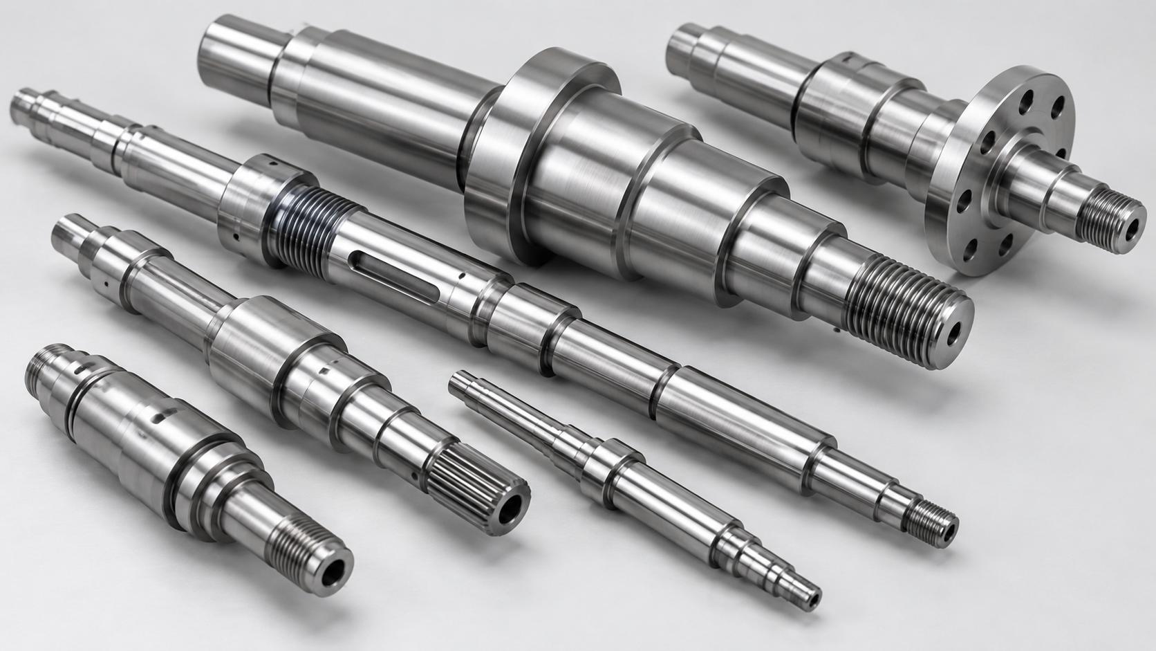
A stepped shaft is a cylindrical component in which the outside diameter changes at one or more positions along its length. These diameter changes create shoulders that can locate bearings, sleeves, gears, collars, seals or other mating components within a mechanical assembly.
Unlike a simple straight rod, a precision stepped shaft is normally manufactured to a finished drawing. Individual diameters, shoulder locations, overall length and their relationship to a common axis can all influence assembly performance.
Why Titanium Is Used for Shaft Components
Titanium offers a useful combination of relatively low density, corrosion resistance and mechanical properties. These characteristics make it an option for custom shafts used in equipment where component weight, environmental resistance or material compatibility is important.
The appropriate titanium grade should follow the customer's engineering requirements. Ti-6Al-4V Grade 5 is commonly used for higher-strength machined titanium components, while commercially pure titanium grades may be specified for projects with different corrosion, fabrication or material requirements.
Typical Features on a CNC Machined Stepped Shaft
| Shaft Feature | Machining Consideration |
|---|---|
| Multiple Diameters | Diameter tolerance and relationship to a common axis |
| Shoulders | Axial position, perpendicularity and corner geometry |
| Grooves | Width, depth, diameter and axial location |
| Threads | Thread type, pitch, length and mating requirement |
| Cross Holes or Flats | Angular position relative to turned features |
| End Features | Chamfers, threads, holes, tapers or drawing-specific geometry |
CNC Turning of Multiple Shaft Diameters
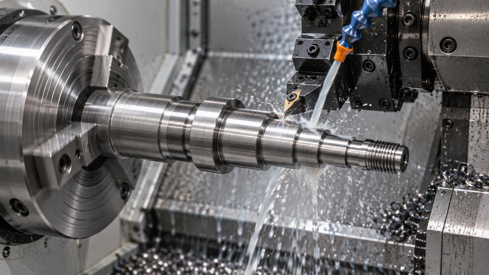
CNC turning is the primary machining process for most stepped shafts. The workpiece rotates while the cutting tool produces the required outside diameters, shoulders, grooves and other rotational features.
Where possible, machining related diameters from a consistent reference setup helps maintain their positional relationship. The production sequence becomes increasingly important as the number of steps and controlled diameters increases.
Concentricity Between Stepped Diameters
A shaft can contain several individual diameters that are each within size tolerance while still creating an assembly problem if their axes are not sufficiently aligned. For this reason, concentricity, runout or other drawing-defined geometric requirements may be important on precision shaft designs.
Critical diameters should be clearly identified on the drawing together with the appropriate datum or inspection requirement. This allows machining and inspection methods to be selected according to the functional relationship of the component.
Shoulder Position and Axial Dimensions
The shoulders created between different shaft diameters often act as axial locating surfaces. A bearing, spacer, sleeve or another component may seat directly against one of these shoulders.
For this reason, shoulder-to-shoulder dimensions can be as important as the shaft diameters themselves. The drawing should specify the required axial dimensions from suitable reference faces rather than relying only on overall shaft length.
Machining Long Titanium Shafts
As the length-to-diameter ratio increases, a shaft can become more sensitive to cutting force and workpiece support. Long, relatively slender components therefore require different machining consideration from short and rigid turned parts.
The appropriate setup depends on the finished diameter, total length, raw material condition and required tolerances. Supporting the workpiece correctly and controlling the machining sequence can help maintain stable dimensions along the shaft.
Turning Small-Diameter Sections
A stepped shaft may transition from a relatively large raw material diameter to a much smaller finished section. Removing significant material to create a long small-diameter feature can make the component more sensitive to machining forces.
Designers should therefore consider both the final geometry and practical manufacturing requirements when specifying very long, thin shaft sections with tight tolerances.
Grooves and Retaining Features
Circumferential grooves may be added for retaining rings, seals, clearance requirements or other assembly purposes. Groove width, root diameter and axial location should be specified according to the mating component.
Where a groove is positioned close to a shoulder, sufficient space for machining and inspection should also be considered during drawing review.
Threaded Titanium Shafts
External or internal threads can be incorporated into one or both ends of a titanium shaft. Common designs include a threaded end for fastening, an internal tapped hole for assembly or a thread combined with a locating diameter.
Thread specification should include size, pitch, class or tolerance when applicable, usable thread length and any required thread relief. The mating component can also be useful when reviewing a custom thread requirement.
Cross Holes, Flats and Milled Features
Some shafts require features that cannot be produced by turning alone. Cross holes, wrench flats, slots, pockets and other non-rotational details can be added through CNC milling or turn-mill machining.
When these features have a defined angular relationship to another hole or flat, the drawing should clearly show the orientation requirement. Coordinated turn-mill machining can be useful for components containing both rotational and milled geometry.
Corner Radii and Undercuts at Shaft Shoulders
The transition between two diameters may contain a radius, chamfer, sharp-defined corner or relief groove according to the design. This detail can influence how a mating bearing, sleeve or collar seats against the shoulder.
Rather than leaving the transition undefined, specifying the required corner geometry helps avoid interference and gives the machinist a clear production reference.
Surface Finish on Functional Diameters
Not every area of a stepped shaft requires the same surface finish. Bearing seats, seal locations and precision mating diameters may have different requirements from non-functional external surfaces.
Identifying functional surfaces individually can prevent unnecessary machining cost while ensuring that the important assembly areas receive the required finish.
Runout and Straightness
For longer shafts or components with several precision diameters, straightness and runout can become important inspection items. The applicable requirement depends on how the shaft is supported and used in the final assembly.
Drawings should identify the relevant datum surfaces and geometric tolerances when these characteristics are functionally important. This provides a clear basis for both production and final inspection.
Machining Titanium Shafts from Bar Stock
Round titanium bar is a practical starting material for many stepped shaft designs. Raw material diameter is normally selected to provide sufficient machining allowance for the largest finished diameter while avoiding unnecessary material removal where possible.
For repeat production, material diameter, cutting length and machining allowance can be reviewed together to improve material utilization and production consistency.
Inspection of Titanium Stepped Shafts
| Inspection Area | Typical Check |
|---|---|
| Stepped Diameters | Individual diameter and drawing tolerance |
| Shoulder Locations | Axial dimensions from defined references |
| Overall Length | Finished end-to-end dimension |
| Grooves and Threads | Size, position and functional fit |
| Geometric Relationship | Runout, concentricity or drawing-defined GD&T |
| Surface Condition | Surface finish, edge condition and burr removal |
Prototype and Small-Batch Shaft Production
New equipment and mechanical projects often require only a few shafts during prototype development. CNC machining allows the geometry to be produced directly from the drawing without requiring tooling intended for high-volume forming processes.
After the prototype dimensions and assembly are confirmed, the CNC program, tooling approach and inspection references can be retained and optimized for subsequent batches.
What to Include in a Titanium Shaft RFQ
Information Helpful for Quotation
Please provide the titanium grade, maximum diameter, stepped diameters, overall length, shoulder locations, threads, grooves, holes or milled features, tolerances, surface finish and required quantity. A PDF drawing together with a STEP model is recommended for shafts containing multiple functional features.
Custom Titanium Shaft Machining from Sunrise Industrial
Sunrise Industrial manufactures stepped shafts, sleeves, bushings, threaded components, flanges, connectors and other drawing-based titanium CNC machined parts. Depending on component geometry, production can combine CNC turning, milling, turn-mill machining, grinding and dimensional inspection for custom OEM projects.
Need Custom Titanium Stepped Shafts?
Send us your shaft drawing, titanium grade, critical diameters, length, tolerance requirements and quantity for machining review and quotation.
Contact UsAbout Sunrise Industrial
Sunrise Industrial is an ISO 9001:2015 precision CNC machining and custom component manufacturer. We manufacture titanium CNC machined parts, prosthetic components, titanium dental discs, titanium sputtering targets, titanium fasteners and other drawing-based custom components for OEM projects.